How to...
Create a project
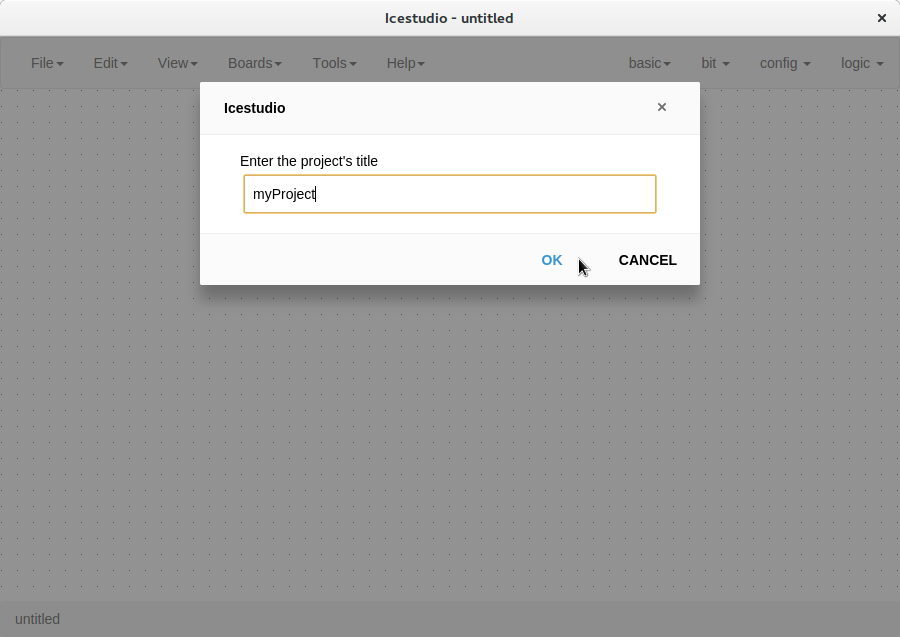
Create a new project
Go to Edit > New project, write your project’s name and press OK.
- Add your blocks
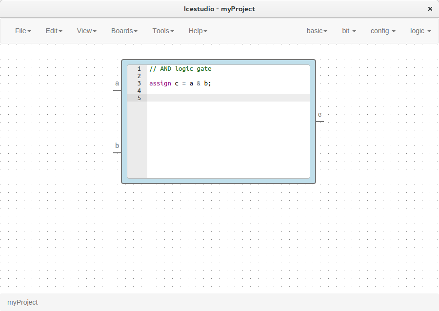
Code blocks
Click on basic > code, add the code ports. Input and output ports are separated by a space. Port names are separated by a comma. E.g.:
a,b c.This block contains a text editor to write your module verilog code. Module header and footer are not required.
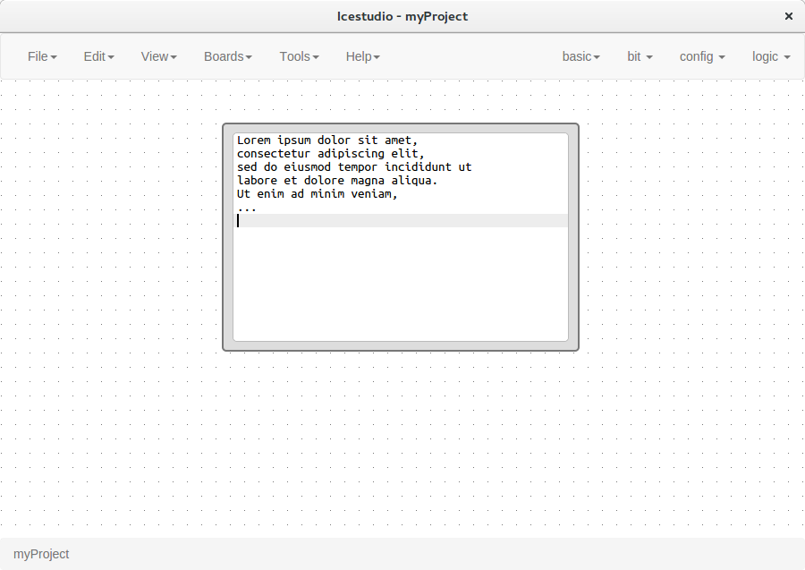
Info blocks
Click on basic > info.
This block contains a text editor to add comments about the project.
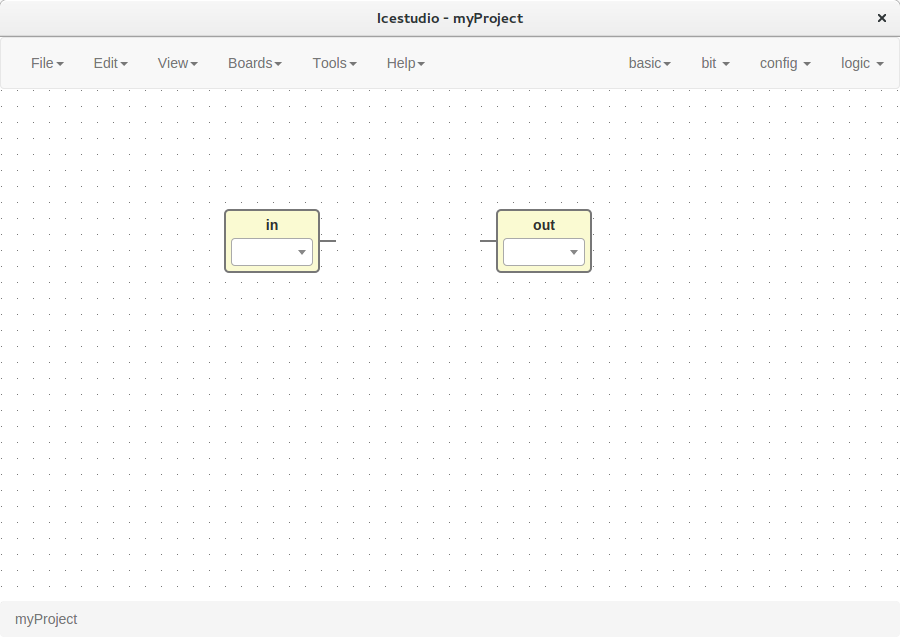
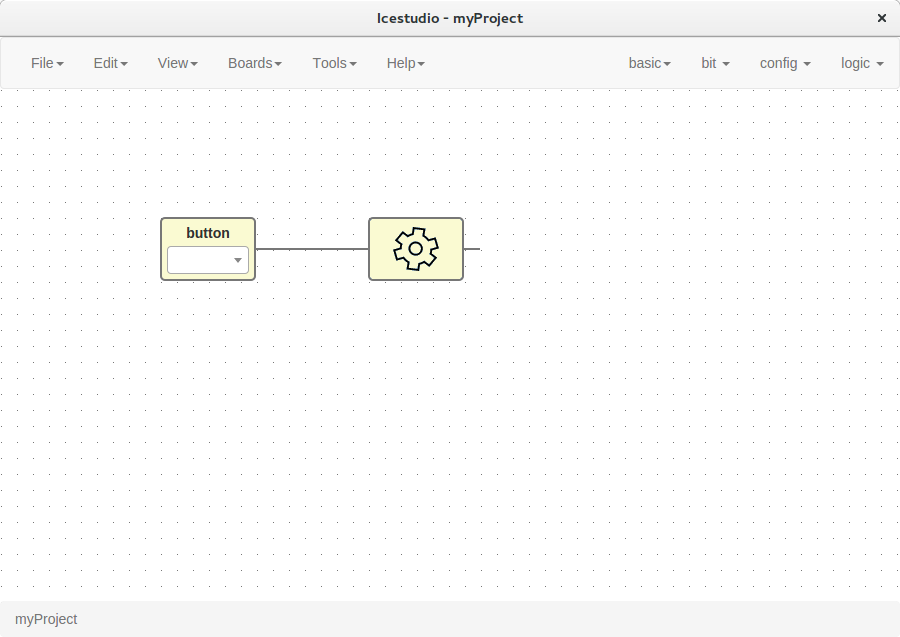
Input/Output blocks
Click on basic > input or basic > output, write the block’s name and press OK.
These blocks contain a FPGA pin selector depending on the selected board.
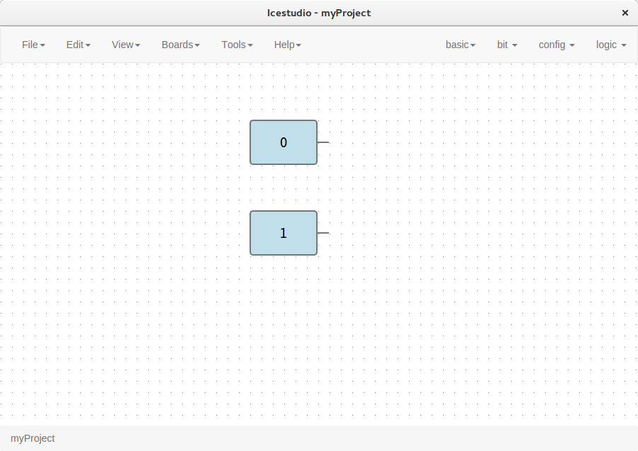
Bit blocks
Click on bit > 0 or bit > 1.
These blocks are low and high logic drivers.
Config block
Click on config > Input-config.
This block must be connected to input ports in order to configure a pull up.
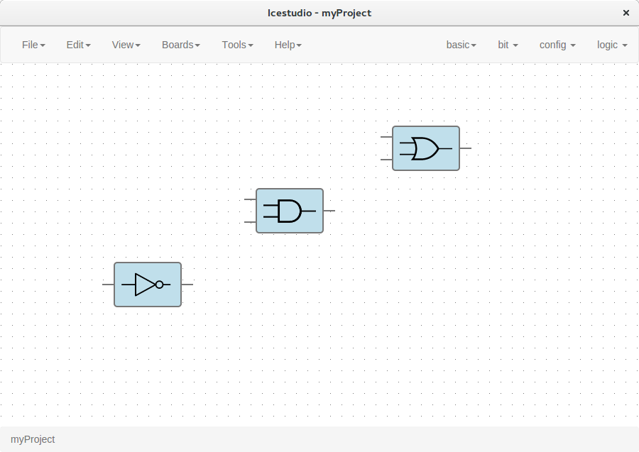
Logic blocks
Go to the logic menu and select a logic gate.
- Connect your blocks
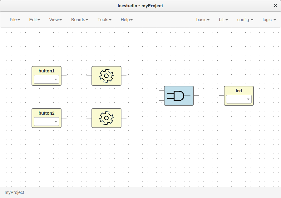

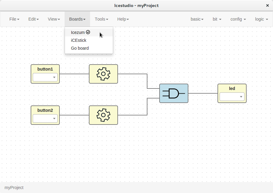
Select your board
Go to Boards menu and select Icezum, iCEstick or Go board.
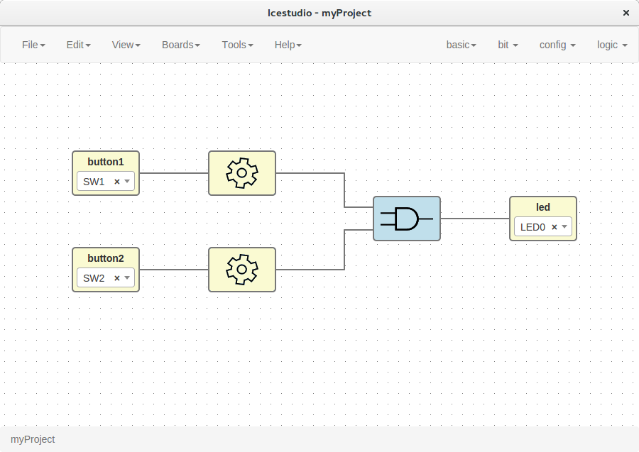
Set FPGA I/O pins
Select all Input/Output blocks’ pins.
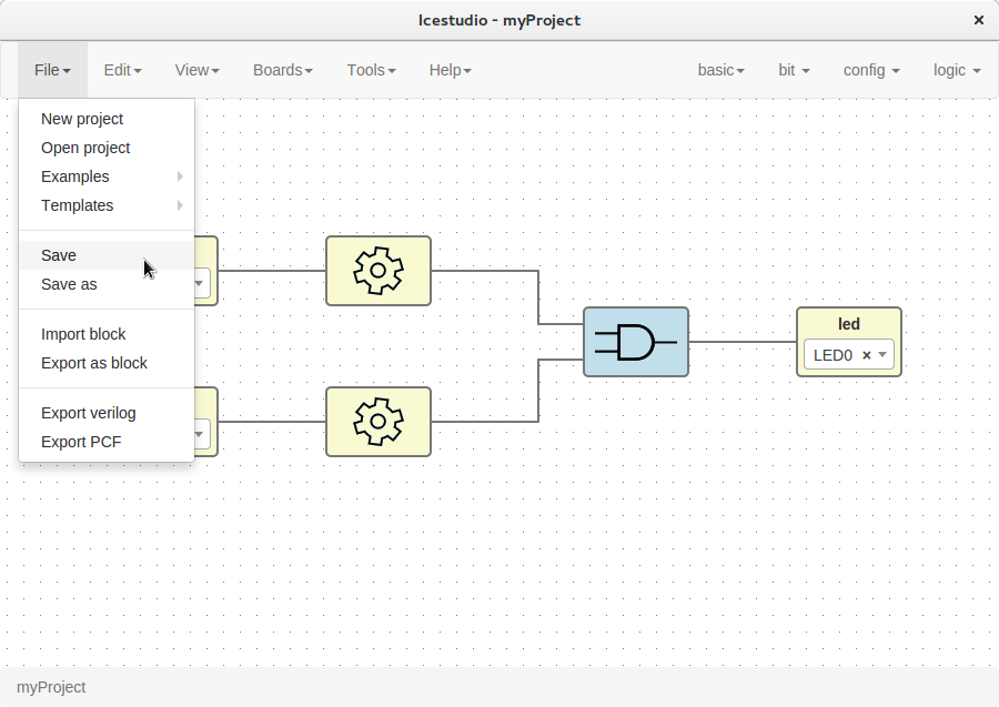
Save the project
Go to Edit > Save:
It will be saved as an .ice file.
Upload a bitstream
Open a project
Go to Edit > Open project and select an .ice file.
Verify the project
Go to Tools > Verify.
This option checks the generated verilog code using
apio verify.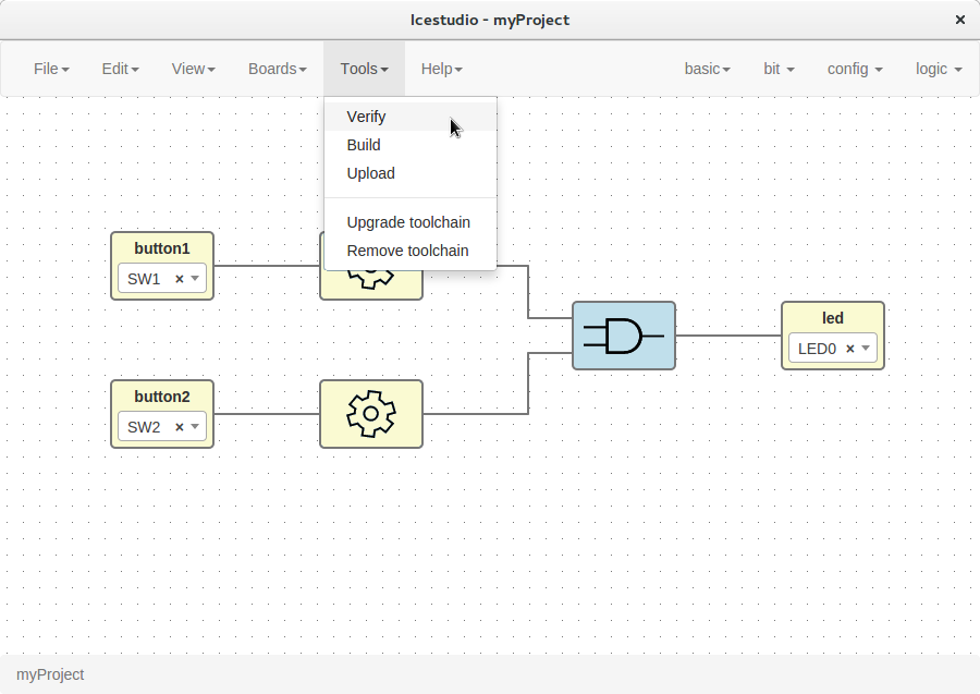
Build the project
Go to Tools > Build.
This option generates a bitstream using
apio build.
Upload the project
Connect your FPGA board and press Tools > Upload. This option uses
apio upload.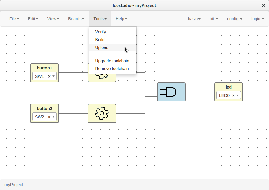
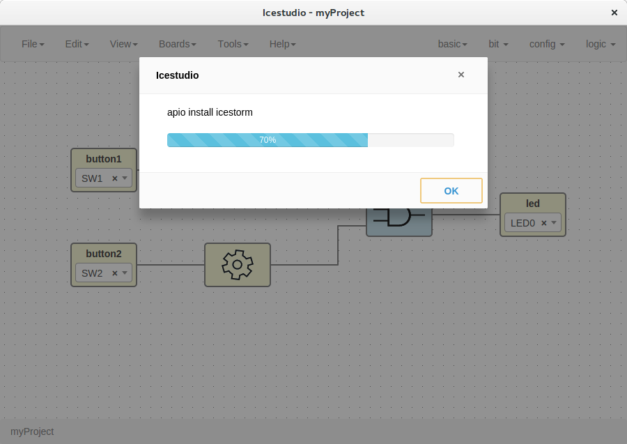
Note
If the FPGA toolchain is not installed, it will be installed automatically when any tool is pressed. It can also be installed or removed in the menu Tools section.
Create a block
Open a project
Go to Edit > Open project and select an .ice file.
Verify the project
Go to Tools > Verify.
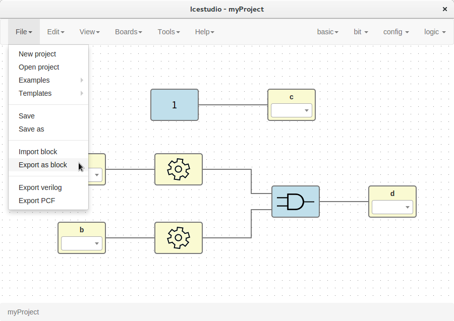
Export the project as a block
Go to Edit > Export as block.
It will be saved as an .iceb file.
Note
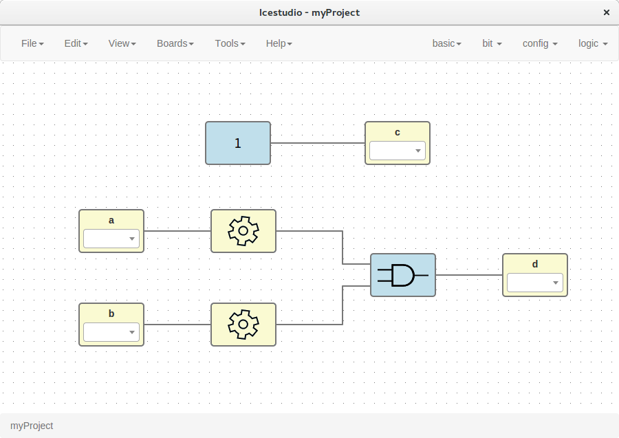
Input/Output blocks will become new Block I/O pins.
Use a custom block
- Open or create a new project
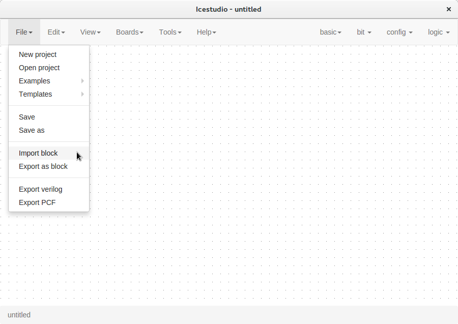
Import the custom block
Go to Edit > Import block and select an .iceb file.
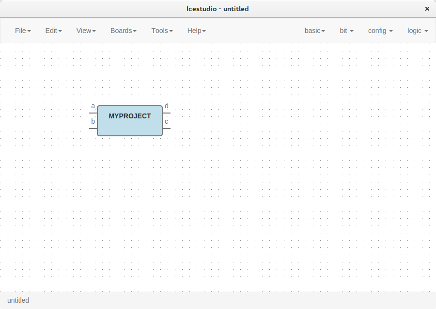
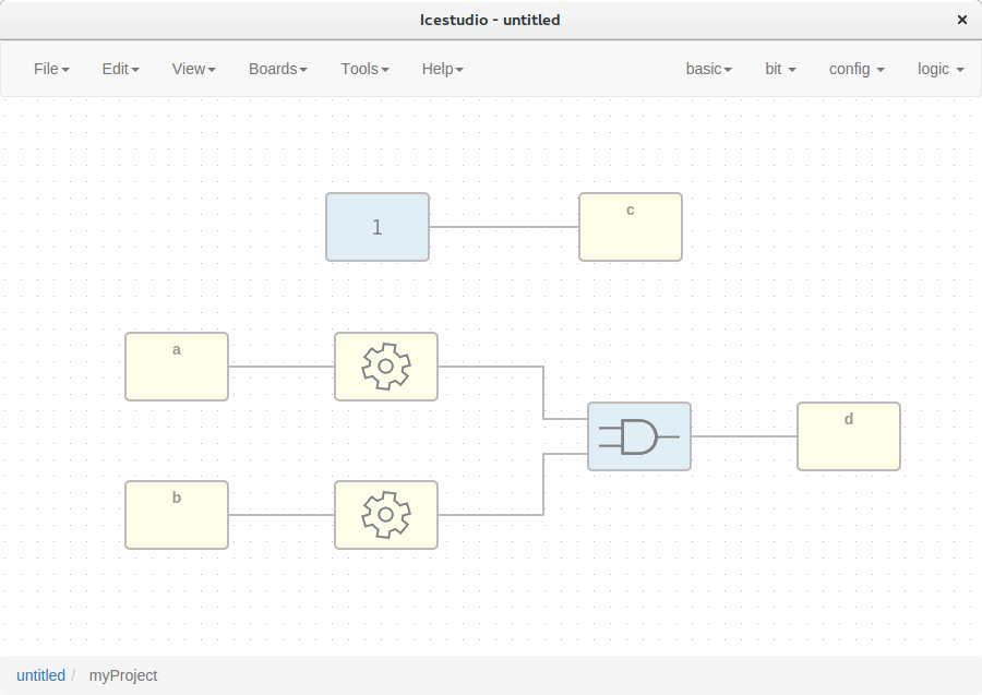
Examine the custom block
Complex blocks can be examined by double clicking the block.
Include a list file
If your code block contains a list file(s), for example:
$readmemh("rom.list", rom);
- Save the ice project
- Copy the list file(s) in the project directory
- Build and upload the project